The dxf file is slightly different to the one that I have used as I have included a large cut out at the drilling point in order that swarf does not jam down the side of the rod and can be cleared easily using an old paint brush during the drilling phase. If you can get the jig parts laser or plasma cut, I can supply a.

If you have access to a foundry, you may be able to have the rods induction hardened for additional life. After drilling is completed, tap each hole in the bar using a first, second and plug tap for each one. This is to ensure that the holes remain properly aligned throughout the length. I recommend that when drilling the 4.2mm holes, that the first hole in the rod is tapped and the first hole in the bar drilled out to 5mm and countersunk, then the rod and bar temporarily fixed together using one of the M5 x 10 bolts before drilling the remainder of the 4.2mm holes. Once all of the 4.2mm holes are drilled down the length of the rail, remove the 16mm rod then redrill each of the holes in the bar using the 5mm drill then countersink each hole using the 10mm drill. You will find it necessary to use supports for the ends of the rod and bar if they are longer than about 750mm as it will be difficult to keep the work pieces flat in the jig otherwise. I seriously recommend that the jig is cleared of metal swarf each time the work pieces are moved up the jig to prevent scratching of the 16mm rod. The positioning jig is then reset to provide 150mm spacing for the holes down the remainder of the rod. The depth stop on the bench drill must be set so that the last 3mm of the rod are not drilled. I used small brass dowels (turned on my lathe) instead which were fitted into additional holes in the jig strips.īoth the bar and the rod are then drilled using the 4.2mm drill. The 25mm bar is centred on the top of the strips and held in the centre by using additional strips either side of the bar and secured by cramps.

To use the jig, the 16mm rod is inserted between the strips with the 'flat' facing upwards and butted against the positioning jig which is at the 75mm position initially. The four holes to the left of the jig strips are drilled so that the positioning jig can be set at an initial 75mm in from the end of the rod and then at 150mm for each successive hole. The jig is positioned on the drill table first by using a 10mm drill into the centre hole. On the drill table beside the jig is a positioning tool made up with two 5mm rods on the outside with an old 4.2mm drill in the centre. This is the jig I made up from a 5mm piece of steel with two strips made up 3 pieces each of 5mm steel bolted together to make the strips 15mm high. If you have access to a small lathe, you will find it useful for turning small pins for your drilling jig.Īlthough it may be possible to do the next operation without a jig, making one is well worth the time and effort to ensure accurate drilling.A set of hex (Allen) keys - preferably ball-ended.

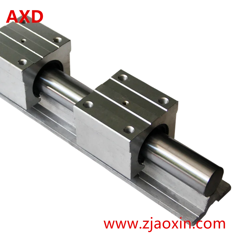
A quantity of M5 x 25mm, countersunk, socket (allen) ended bolts to suit length of rails.A quantity of M5 x 10mm, countersunk, socket (allen) ended bolts to suit length of rails.4.2mm, 5mm and 10mm (for countersinking) drill bits.If this is not available, there are many different lengths of cheap, 'I' sectioned spirit levels up to 1800mm (or more) length and with milled edges available on eBay. I used dividing strips from demountable office partitions that I got from my local junk yard. 2 x Aluminium 'I' section support rails.2 x 25mm x 5mm, bright steel bar to same length as steel rod.(sufficient to provide support at 150mm intervals along whole length of rail. 12.5mm x 8mm electrical stand-off spacers.2 x 16mm, bright steel rod cut to required length or other smooth finished 16mm steel bar that can be bored and threaded with a hand tap.The following tools and parts will be required for this part of the project:


 0 kommentar(er)
